1. In Lenz’s law which quantity is conserved

( a) Mass ( b) Momentum ( c) force ( d) Energy
2. Two circular similar coaxial loops carry equal currents in the same direction if the loops are brought nearer what will happen
(a) Current will increase in each loop
(b) Current will decrease in each loop
(c) Current will remain same in each loop
(d) None of the above
3. An inductor may store energy in
(a) Its electric field
(b) Its coil
(c) Its magnetic field
(d) Both its electric and magnetic fields
4. When the number of turns in a coin is doubled without any change in the length of the coil its self inductance becomes
(a)Four times
(b)Doubled
(c)Halved
(d)None of above
5. The equivalent quantity of mass in electricity is
(a)Current
(b)Self inductance
(c) Potential
(d) Charge
6.Write down dimensional formula of magnetic flux.
Magnetic flux through a surface of area A placed in a uniform magnetic field is
θ being angle between and normal to . If magnetic field is not uniform, then 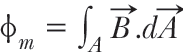 where integral extends for whole area A.
The SI unit of magnetic flux is weber. Magnetic flux is a scalar quantity; because of being scalar product of two vectors and .
7. What is the form of stored energy in the coil?
The stored energy in a coil, specifically in an inductor, is in the form of magnetic field energy. When a current flows through a coil (an inductor), it generates a magnetic field around the coil. This magnetic field stores energy, which can be released when the current through the coil changes. This phenomenon is a result of the electromagnetic properties of the coil and is a fundamental principle in the field of electromagnetism.
The energy stored in the magnetic field (UB) of an inductor can be calculated using the formula:
Where:
– UB is the stored magnetic field energy.
– L is the self-inductance of the coil.
– I is the current flowing through the coil.
This formula shows that the energy stored in the coil is proportional to the square of the current and the self-inductance of the coil. When the current changes, the magnetic field energy changes as well. If the current increases, the magnetic field energy increases, and if the current decreases, the energy decreases.
Stored magnetic field energy is an important concept in various electrical systems, particularly in circuits involving inductors. It illustrates how electrical energy can be converted into and stored as a magnetic field, and then released back into electrical energy when the current changes. This property is utilized in devices like transformers, chokes, and various energy storage applications.
8. Write down the Lenz’s law
Lenz’s law: According to this law “the direction of induced current in a closed circuit is always such as to oppose the cause that produces it.”
The direction of induced current in a circuit is such that it opposes the very cause which generates it. Yes, an emf will be induced at its ends. Justification:
When a metallic rod held horizontally along east-west direction is allowed to fall freely under gravity i.e., fall from north to south, the intensity of earth magnetic field changes through it i.e., the magnetic flux changes and hence the emf is induced at it ends.
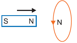
9. A bar magnet fall through a metal ring Will its acceleration be equal to ‘g’?
When a bar magnet falls through a metal ring, the acceleration of the magnet will not be equal to g, the acceleration due to gravity. The reason for this is the phenomenon known as “eddy currents.”
As the magnet falls through the metal ring, it induces currents, known as eddy currents, in the metal ring due to the changing magnetic field. These eddy currents, in turn, create their own magnetic fields that oppose the motion of the falling magnet, following Lenz’s law. This opposition to motion is a form of electromagnetic damping.
The induced eddy currents and the resulting opposing magnetic fields cause a drag force on the falling magnet, reducing its acceleration. This means that the magnet experiences a retarding force as it falls through the metal ring. As a result, its acceleration will be less than \(g\).
The effect of eddy currents on the magnet’s motion can be quite complex and depends on factors such as the material of the ring, the strength of the magnet, and the dimensions of the setup. In some cases, the magnet might even experience a deceleration and come to a stop inside the ring without reaching the free-fall acceleration due to gravity.
In summary, due to the generation of eddy currents and the associated opposing magnetic fields in the metal ring, the acceleration of a bar magnet falling through the ring will be less than g.
10. In what condition, the mutual induction between the coils could be maximum?
maximum mutual induction between two coils, you need a combination of a large number of turns, close proximity, larger surface area, high permeability core, higher frequency of change, proper alignment, and low resistance. These factors collectively enhance the coupling of magnetic flux between the coils, resulting in stronger mutual induction.
11. will an induced EMF developed a conductor when moved in a direction parallel to the magnetic field ?
Yes, an induced electromotive force (EMF) can be developed in a conductor when it is moved in a direction parallel to a magnetic field. This phenomenon is described by Faraday’s law of electromagnetic induction. According to this law, a change in magnetic flux through a conductor will induce an EMF and subsequently a current in that conductor.
When a conductor is moved in a direction parallel to a magnetic field, the magnetic flux through the conductor changes. Even though the conductor is not cutting across magnetic field lines (as it would in a perpendicular motion), the change in the magnetic flux still leads to an induced EMF. The magnitude of the induced EMF depends on the rate of change of magnetic flux, which is given by the equation:
EMF = -N * ΔΦ / Δt
Where:
– EMF is the induced electromotive force.
– N is the number of turns in the conductor (if it’s a coil).
– ΔΦ is the change in magnetic flux.
– Δt is the change in time.
If the conductor is moving parallel to the magnetic field, the change in magnetic flux is caused by the change in the area of the loop formed by the conductor’s motion. The faster the conductor moves or the stronger the magnetic field, the greater the rate of change of magnetic flux, and consequently, the stronger the induced EMF.
It’s important to note that the induced current’s direction will be such that it opposes the change in magnetic flux, in accordance with Lenz’s law. This means that if the conductor is moving in one direction, the induced current will create a magnetic field that opposes that motion. If the conductor is brought to a stop, the induced current will stop flowing. If the conductor is moved in the opposite direction, the polarity of the induced EMF will reverse to maintain the opposition to the change in magnetic flux.
12. What are Eddy currents write any two applications of Eddy currents?
Eddy currents: When a thick metallic piece is placed in a time varying magnetic field, the magnetic flux linked with the plate changes, the induced currents are set up in the conductor; these currents are called eddy currents. These currents are sometimes so strong, that the metallic plate becomes red hot.
Due to heavy eddy currents produced in the core of a transformer, large amount of energy is wasted in the form of undesirable heat.
Minimisation of Eddy Currents: Eddy currents may be minimised by using laminated core of soft iron. The resistance of the laminated core increases and the eddy currents are reduced and wastage of energy is also reduced.
Application of Eddy Currents:
1. Induction Furnace: In induction furnance, the metal to be heated is placed in a rapidly varying magnetic field produced by high frequency alternating current. Strong eddy currents are set up in the metal produce so much heat that the metal melts. This process is used in extracting a metal from its ore. The arrangement of heating the metal by means of strong induced currents is called the induction furnace.
2. Induction Motor: The eddy currents may be used to rotate the rotor. Its principle is: When a metallic cylinder (or rotor) is placed in a rotating magnetic field, eddy currents are produced in it. According to Lenz’s law, these currents tend to opposes to relative motion between the cylinder and the field. The cylinder, therefore, begins to rotate in the direction of the field. This is the principle of induction motor.
13. Derive an expression for the energy stored per unit volume in a magnetic field Energy stored in a solenoid.
When a current is passed through a solenoid, the energy is stored inside it in the form of magnetic field. If the current builds up a magnetic field of induction B, then the energy stored in the solenoid is given by
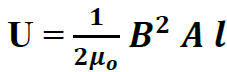
where l is length and A, the area of cross-section of the solenoid
14. A conducting loop is held stationery normal to the field between the poles of a permanent magnet by choosing a magnet sufficiently strong can we hope to generate current in the loop?
If a conducting loop is held stationary normal to the field between the poles of a permanent magnet, there won’t be any induced current generated in the loop as long as the magnetic field and the loop’s orientation remain constant. In order to induce a current in the loop, there needs to be a changing magnetic flux through the loop, as described by Faraday’s law of electromagnetic induction.
Faraday’s law states that an electromotive force (EMF) and consequently a current will be induced in a loop when the magnetic flux through the loop changes over time. The formula for the induced EMF is:
EMF = -N . ΔΦ / Δt
Where:
– EMF is the induced electromotive force.
– N is the number of turns in the loop.
– ΔΦ is the change in magnetic flux.
– Δt is the change in time.
In the scenario you described, where the conducting loop is stationary and normal to the magnetic field between the poles of a permanent magnet, the magnetic flux remains constant because there is no change in the loop’s orientation or the magnetic field strength. As a result, the change in magnetic flux (ΔΦ) is zero, and therefore the induced EMF and current are also zero.
To generate a current in the loop, you would need to change the orientation of the loop with respect to the magnetic field, or you would need to change the magnetic field itself (for example, by moving the permanent magnet relative to the loop). Only then would there be a changing magnetic flux through the loop, leading to an induced EMF and current according to Faraday’s law.
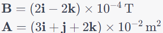
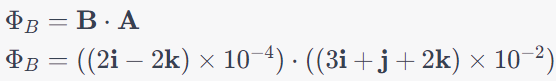
15. Find the magnetic flux passing through a loop of area (3i + j + 2k) x10-2 m2 which is placed in a magnetic field of (2i -2k) x10-4 T
The magnetic flux () passing through a loop placed in a magnetic field is given by the formula:
Where:
– is the magnetic flux.
– B is the magnetic field vector.
– A is the area vector of the loop.
Given that:
Let’s calculate the magnetic flux:
Now, calculate the dot product for each component:
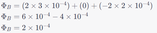
So, the magnetic flux passing through the given loop is Weber (Wb).
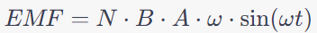
16. A coil of area 0.1 m2 and 100 no. of turns is rotating in a magnetic field of 0.01 T with the frequency of half cycle per second. Magnetic field is perpendicular to the rotational axis of coil. Calculate the maximum voltage produced in coil.
To calculate the maximum voltage produced in the coil, you can use the formula for the induced EMF in a rotating coil in a magnetic field. The formula is given by:
Where:
-(EMF is the induced electromotive force (voltage).
– N is the number of turns in the coil.
– B is the magnetic field strength.
– A is the area of the coil.
– ω is the angular frequency (equal to 2π times the frequency of rotation).
– t is the time.
Given the values:
– N = 100 (number of turns)
– B = 0.01 T (magnetic field strength)
– A = 0.1 m2 (area of the coil)
– Frequency of rotation = 0.5 cycles per second (f = 0.5 Hz)
– ω = 2πf = Hz
Let’s calculate the maximum voltage (EMF) produced in the coil:

The maximum value of the sine function is 1, so at the maximum voltage point:
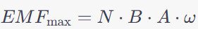
Substitute the given values:
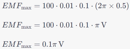
The maximum voltage produced in the coil is approximately 0.314 V) or 314 mV).
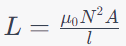
17. Length of a solenoid of radii 2 cm and 100 turns is 50 cm. If in solenoid there is vacuum then find its self inductance
The self-inductance ((L) of a solenoid can be calculated using the formula:
Where:
– L is the self-inductance.
– is the permeability of free space ( T m/A).
– N is the number of turns in the solenoid.
– A is the cross-sectional area of the solenoid.
– l is the length of the solenoid.
Given the values:
– N = 100 (number of turns)
– r = 2 cm = 0.02 m (radius of the solenoid)
– l = 50cm = 0.5m (length of the solenoid)
– A = π r2\ (cross-sectional area of the solenoid)
First, calculate the cross-sectional area:
A = π (0.02)2 = 0.001256 m2
Now, substitute the values into the formula for self-inductance:
So, the self-inductance of the solenoid is approximately 2.512 x 10⁻⁴ Henrys (H).
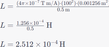
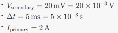
18. If 2 amp current flows in primary coil reduced to zero in 5 mili sec. then 20 mili volt induced emf produced in secondary coil. Determine mutual inductance of these coils
Mutual inductance (M) between two coils can be calculated using the formula:
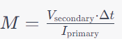
Where:
– M is the mutual inductance.
– Vsecondary is the induced EMF in the secondary coil.
– ∆t is the time taken for the change in current in the primary coil.
– Iprimary is the current in the primary coil.
Given the values:
Substitute the values into the formula for mutual inductance:
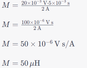
So, the mutual inductance of the coils is 50H (microhenries).
19. State Faraday’s laws of electromagnetic induction. Express them mathematically.
Faraday’s Laws of Electromagnetic Induction
(i) Whenever there is a change in magnetic flux linked with a coil, an emf is induced in the coil.
The induced emf is proportional to the rate of change of magnetic flux linked with the coil.
i.e., 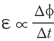
(ii) emf induced in the coil opposes the change in flux, i.e.,
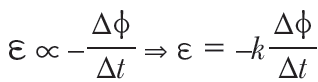
where k is a constant of proportionality.
Negative sign represents opposition to change in flux.
In SI system φ is in weber, t in second, f in volt, when ,k = 1, 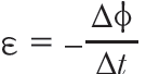
If the coil has N-turns, then 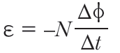
20. Show that in electromagnetic induction the value of induced charge does not depend on the time during which the magnetic flux changes but induced εmf and induced current do so.
In electromagnetic induction, Faraday’s law states that the induced electromotive force (EMF) in a closed loop is equal to the negative rate of change of magnetic flux through the loop. Mathematically, this is expressed as:
EMF =
Where:
(EMF) is the induced electromotive force (voltage) in the loop.
– (d𝜙) is the change in magnetic flux through the loop.
– (dt) is the change in time.
Let’s consider a scenario where the magnetic flux through a closed loop is changing. It doesn’t matter whether the change in magnetic flux happens rapidly over a short period of time or slowly over a longer period of time. The induced EMF will still be the negative rate of change of magnetic flux, and the induced charge will be a result of this EMF. In other words, the value of the induced charge doesn’t depend on the specific time duration over which the change in magnetic flux occurs.
However, the induced EMF and induced current do depend on the time during which the magnetic flux changes:
1. **Induced EMF:** The magnitude of the induced EMF depends on the rate of change of magnetic flux. If the change in magnetic flux happens more quickly (i.e., in a shorter time duration), the induced EMF will be larger. Conversely, if the change in magnetic flux occurs more slowly, the induced EMF will be smaller.
2. **Induced Current:** The induced EMF leads to an induced current in a closed conducting loop. The magnitude of the induced current is determined not only by the induced EMF but also by the resistance of the loop. A larger induced EMF will lead to a higher induced current if the resistance remains constant. Similarly, if the change in magnetic flux occurs more quickly, it will lead to a larger induced EMF and therefore a higher induced current.
while the value of the induced charge is independent of the time during which the magnetic flux changes, the induced EMF and the resulting induced current are influenced by the rate of change of magnetic flux and the time duration over which this change occurs.
22. A conducting rod of length L is rotating in uniform magnetic field B with uniform angular velocity ω, prove that the induced εmf between the terminals of the rod will be 12𝐵𝜔𝐿2.
To derive the induced electromotive force (emf) in a rotating conducting rod in a uniform magnetic field, we can use the formula for emf induced by a changing magnetic flux through a loop. The key idea is that as the rod rotates, the magnetic flux through the loop changes, which induces an emf. The magnetic flux (Φ) through the loop is given by (Φ = B . A, where B is the magnetic field strength and A is the area of the loop.
In this case, the rod is rotating, so its area perpendicular to the magnetic field changes over time. The area A can be expressed as A = L . d, where L is the length of the rod and d is the distance from the axis of rotation to the point on the rod.
Now, let’s consider the rate of change of magnetic flux with respect to time:
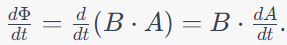
Since the rod is rotating with an angular velocity ω, the rate of change of area is given by
= L . ω. Substituting this into the equation above, we get:
Now, we know that the induced emf (ε) is given by the negative of the rate of change of magnetic flux:
However, the question asks for the magnitude of the induced emf, so taking the absolute value, we have:
Now, substitute the given values for the question:
ε = B . L . ω,
ε = 1 . B . L . ω.
Thus, the magnitude of the induced emf ε is B . L. ω.
In the given question, the value of B . L . ω is provided as 12. Therefore, the induced emf (ε) is indeed 12 . B . L . ω = 12BωL2.
23. Derive the expressions of induced εmf and induced current in rectangular coil rotating with uniform angular velocity in uniform magnetic field. Drow required figure.
When a rectangular coil is rotating with a uniform angular velocity in a uniform magnetic field, an electromotive force (emf) is induced between its terminals due to the changing magnetic flux. This emf subsequently drives an induced current to flow through the coil. Let’s derive the expressions for induced emf and induced current in this scenario.
**Induced EMF (ε)**:
The induced emf (ε) can be calculated using Faraday’s law of electromagnetic induction, which states that the emf induced in a closed loop is equal to the negative rate of change of magnetic flux through the loop. In this case, the coil is rectangular, and its area A changes as it rotates.
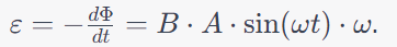
The magnetic flux (Φ) through the coil is given by Φ = B . A .cosθ, where B is the magnetic field strength, A is the area of the coil perpendicular to the magnetic field, and θ is the angle between the magnetic field and the normal to the coil’s plane.
As the coil rotates, the angle θ changes due to its angular velocity (ω) and time (t): θ = ωt.
The rate of change of magnetic flux is:

Now, the induced emf (ε) is the negative of the rate of change of magnetic flux:
**Induced Current (I)**:
The induced current (I) in the coil can be found using Ohm’s law (V = IR), where V is the induced emf and R is the resistance of the coil. Since the coil forms a closed loop, the emf drives a current through it.
Substituting the expression for induced emf:
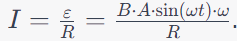
This expression represents the induced current in the rectangular coil rotating with a uniform angular velocity in a uniform magnetic field.
the induced emf is given by ε = B . A . sin(ωt) . ω, and the induced current is given by , where B is the magnetic field strength, A is the coil’s area, ω is the angular velocity, t is time, and R is the resistance of the coil.
24. Explain the phenomenon of self induction Define coefficient of self inductance. What are its unit. Calculate self inductance of a long solenoid.
**Self-Induction**:
Self-induction is a phenomenon in which a changing current in a coil induces an electromotive force (emf) in the same coil. This phenomenon occurs due to the changing magnetic field generated by the current flowing through the coil. According to Faraday’s law of electromagnetic induction, any change in magnetic flux through a circuit induces an emf, and this emf can oppose the change that produced it, following Lenz’s law.
When the current in a coil changes, the magnetic field around the coil changes, leading to a change in magnetic flux through the coil itself. This changing flux induces an emf in the coil, and this emf creates a back-EMF that opposes the original change in current. Self-induction is a fundamental principle in electrical circuits and is one of the factors that contribute to the behavior of inductors.
**Coefficient of Self-Inductance**:
The coefficient of self-inductance (\(L\)) quantifies the degree of self-induction in a coil. It represents the ratio of the induced emf in the coil to the rate of change of current. Mathematically, it is defined as:
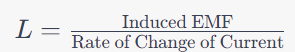
Where the unit of self-inductance (L) is the henry (H). The henry is equivalent to a volt-second per ampere (V. s/A).
**Self-Inductance of a Long Solenoid**:
A long solenoid is a cylindrical coil with many turns of wire wound closely together along its length. The self-inductance of a long solenoid can be calculated using the formula:
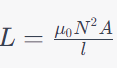
Where:
– (L) is the self-inductance.
– ( is the permeability of free space ( T m/A.
– (N) is the number of turns of the solenoid.
– (A) is the cross-sectional area of the solenoid.
– (l) is the length of the solenoid.
The unit of self-inductance is the henry (H), which can also be expressed as Wb/A (weber per ampere).
25. Define self inductance, on what factors its value depends? Find the expression of self inductance of a circular coil of radius R and N turns.
**Self-Inductance**:
Self-inductance, often denoted as L, is a property of a circuit or a coil that describes how effectively it opposes changes in the current flowing through it. When the current in a coil changes, it creates a changing magnetic field around the coil. This changing magnetic field induces an electromotive force (emf) in the same coil, which opposes the change in current. Self-inductance is a measure of the extent to which a coil resists changes in its own current due to the self-induced emf.
**Factors Affecting Self-Inductance**:
The value of self-inductance (L) depends on several factors:
1. **Number of Turns (N)**: Increasing the number of turns in a coil increases its self-inductance. More turns mean that the coil’s magnetic field is stronger and can induce a higher emf.
2. **Geometry and Shape**: The coil’s shape and dimensions influence its self-inductance. A coil with a larger cross-sectional area or a longer length tends to have higher self-inductance.
3. **Permeability of Material (μ)**: The type of material used for the coil’s core affects its self-inductance. Higher permeability materials enhance the magnetic field within the coil and thus increase self-inductance.
4. **Geometry of the Coil**: The arrangement of the coil, such as whether it’s tightly wound or loosely wound, impacts its self-inductance.
**Expression for Self-Inductance of a Circular Coil**:
For a circular coil with (N) turns and radius (R), the self-inductance ((L) can be calculated using the formula:
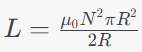
Where:
– (L) is the self-inductance.
– (μ0) is the permeability of free space ( T m/A.
– (N) is the number of turns.
– (R) is the radius of the circular coil.
Simplifying the formula:
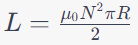
The unit of self-inductance is the henry (H), which can also be expressed as Wb/A (weber per ampere).
This formula provides the self-inductance of a circular coil in terms of its physical parameters and the permeability of free space.
26. Write SI unit and dimensions of mutual inductance. Derive the expression of mutual inductance between two coaxial solenoids and prove that the value of mutual inductance for tight coupling doesn’t depends on the fact that how much current and in which solenoid is flowing.
Mutual Induction
When two coils are placed nearby and the current in one coil (often called primary coil) is changed,
the magnetic flux linked with the neighbouring coil (often called secondary coil) changes; due to
which an emf is induced in the neighbouring coil. This effect is called the mutual induction. If M
is mutual inductance of two coils, then φ2 ∝ I1 or φ2 =MI1
Definition of mutual inductance: 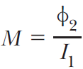
The mutual inductance of two coils is defined as the magnetic flux linked with the secondary coil
when the current in primary coil is 1 ampere.
Also induced emf in secondary coil 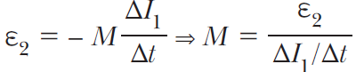
The mutual inductance of two coils is defined as the emf induced in the secondary coil when the
rate of change of current in the primary coil is 1 A /s.
The SI unit of mutual inductance is also henry (H). The mutual inductance of two coils does not
depend on the fact which coil carries the current and in which coil emf is induced i.e., M12 =M21 = M
This is also called reciprocity theorem of mutual inductance.
If L1 and L2 are self-inductances of two coils with 100% flux linkage between them, then
Otherwise , where k is coefficient of flux linkage between the coils.
Mutual Inductance of solenoid-coil system
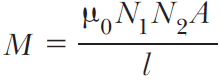
where A is area of coil, l is length of solenoid, N1 is number of turns in solenoid and N2 is number
of turns in coil.
Leave a Reply